Richard Jacklin, Global Sales and Business Development Director, and Craig Somach, Director of Sales, ViaLite Communications
Comm Links optimization via RF over Fiber Backhaul
Military and commercial aerospace businesses involved with the testing of multiple and simultaneously present powered flying objects, such as manned aircraft, drones or missiles, need to be able to receive and send telemetry data during the entire course of the test flights. By its remote nature, this can be accomplished wirelessly using radio communications systems to provide high quality communication links with no signal dropouts or data corruptions. This article describes the optimization of these links through a RF over fiber backhaul system ensuring high fidelity and wide dynamic range.
Frequency use in mil-aero applications
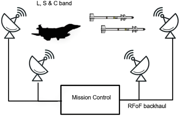
Figure 1. A typical Mil-Aero telemetry system using RFoF across backhaul
In the case of Military Aerospace applications, the Air Force, Navy and Army facility radio systems often work simultaneously across frequencies in all of the P, L, S and C-bands, so in effect, have multiple wideband frequency coverage up to at least 6 GHz.
The telemetry antennas utilized can be of various types including parabolic dishes and directional horn feed antennas. This type of telemetry setup is also known as boresight communications and testing.
When the physical nature of the deployment prohibits the use of coaxial cables to transport the RF signals due to high cable losses and RF immunity concerns, the signals received need to be sent to the mission control room through an RF over fiber (RFoF) backhaul network, to be analyzed and recorded. The mission control room can also be used to transmit RF signals back out, making the system bi-directional and a more challenging design, since receive signals are very low power and transmit signals need to be much higher power. The ability to add additional low noise amplification for the transmit signal is not always available.
Why is RF over fiber used in the backhaul?
Fundamentally, it’s due to distances and the frequencies used. Linking the telemetry antennas to the mission control can involve distances up to a number of kilometers. Using frequencies up to 6 GHz across long distance makes traditional RF coaxial cable far too lossy and not appropriate to the task. RF over fiber has the advantage of super low loss at 0.2 dB/km and can easily cope with the wide frequency bandwidth of multiple and simultaneous telemetry signals. RFoF also benefits from a very small conversion delay with very low signal dispersion.
This is very important for the Mil-Aero application where fast moving objects can affect the radio signal though frequency Doppler shift, multipath propagation and shadowing; critically ensuring that the backhaul connection does not add to these negative effects. The fiber optic cable is also a very inexpensive and lightweight medium, it is extremely stable across different environmental conditions and offers RF immunity, as an added benefit. Crucially the RFoF solution is an analog technique; none of the received signal information is encoded digitally, and neither is it encoded into IP protocol which can be seen as a cyber-vulnerability. The technique of using RFoF in this Mil-Aero telemetry backhaul application is not new. The key questions are:
» What makes a good performing link and under what conditions?
» How do you design and optimize the RFoF system for an uplink, downlink or different types of aerospace vehicle telemetry and tracking?
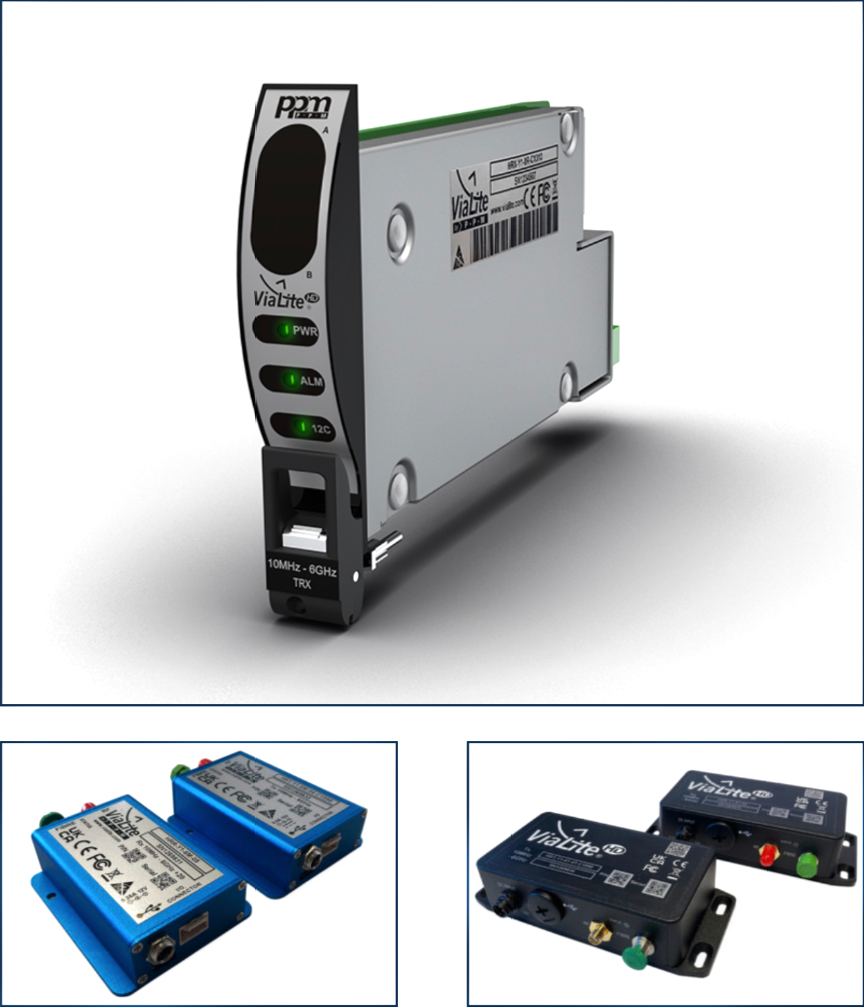
 Figure 2. Typical SFDR measurement from ViaLite 6 GHz Mil-Aero link pair
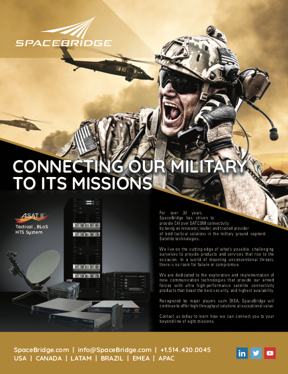
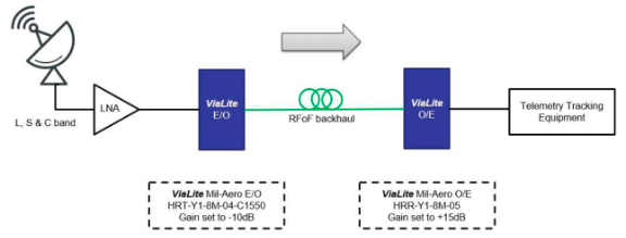 Figure 3. ViaLite Mil-Aero 6 GHz standard gain link pair
Mil-aero 6 ghz rf over fiber link pair
ViaLite Communications introduced a product line specifically aimed at the Mil-Aero telemetry market to address these needs. ViaLite’s Mil-Aero 6 GHz Link Pair (photos below — Form factors: Rack Chassis Card, Blue OEM and Black OEM). (photos below — Form factors: Rack Chassis Card, Blue OEM and Black OEM). This product actually covers the full frequency range from 10 MHz through to 6 GHz without sacrificing Noise Figure (NF) or reduction in Spurious Free Dynamic Range (SFDR). Traditional coaxial cable systems have a challenge under similar conditions. The link comes in various form factors*; OEM module, rack card for use in a chassis, and a uniquely integrated module with an IP55 (Ingress Protection) rating for outdoor use without the need for an additional outdoor enclosure.
Use CASE #1 – telemetry downlink traffic
For the typical telemetry downlink path it’s important that the RF-to-Optical (E/O) transmitter is able to handle objects that pass “close-in”, such as an aeroplane taxiing near a boresight antenna, which may present signals up to 0 dBm after the first LNA stage.
The Mil-Aero 6 GHz Link Pair, for this circumstance, has the default transmitter gain set to -10 dB and the Optical-to-RF (O/E) receiver set to +15 dB. With a lossless optical connection, this provides a link gain of +5 dB. With real-life connection losses, this would be closer to a 0 dB unity link gain.
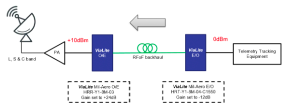 Figure 4. ViaLite 6 GHz Mil-Aero high output link pair
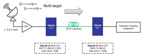 Figure 5. ViaLite 6 GHz Mil-Aero high gain link pair
For the telemetry uplink path, higher power RF signals are typically output from the Telemetry Tracking equipment which, in turn, needs to be connected to the input of an uplink Power Amplifier (PA) positioned near the antenna. Higher RF power levels need to be treated with care, particularly as they get closer to P1dB compression level and harmonic components increase. Typically the system performance would need these harmonic components to be 35dB less than the wanted carrier signal.
In the example shown in Figure 4, the ViaLite transmitter (E/O) is set to -12 dB gain (attenuation) with the ViaLite receiver (O/E) set to +24 dB. These precisely optimized gain settings (from factory default gain settings) can be adjusted in a live field setting using a readily available USB-C cable and simple PC software when using ViaLite Blue or Black OEM modules, or they can be adjusted through software commands if using a ViaLite 19 inch rack SNMP enabled solution.
Use CASE #3 – telemetry, multiple targets operating In C-band
In this use case example, the application scenario requires tracking multiple simultaneous flying objects and at a long distance away from the antenna, operating in C-Band. This situational solution requires a high sensitivity, high gain front end, with a low Noise Figure.
This enables the Telemetry Tracking equipment to pick up the smallest level RF signals, all present at the same time and possibly very near to each other. C-band frequency communication presents superior performance in terms of signal dispersion, but can suffer more with signal shadowing, so minimizing the signal black out is essential.
In the example shown in Figure 5, the ViaLite transmitter (E/O) is set to +5 dB (which helps to provide a lower NF and added sensitivity) and the ViaLite receiver (O/E) is set to +15 dB, thereby giving a link gain of +20 dB (minus any fiber connectivity losses).
Conclusion

This article has described the radio telemetry application known as boresight communications and testing, as applied to flying objects at aeronautical test ranges. ViaLite produces a range of specialist RF over fiber links aimed specifically at backhauling the boresight telemetry signals from the antenna through to the mission control room. These links need to have superior bandwidth, dynamic range and low Noise Figure in order to maintain telemetry link quality and minimize signal black-out. The RF over fiber links also need to accommodate the specific requirements for the uplink and downlink signal dynamics in power level and harmonic content.
Authors: Richard Jacklin is the Global Sales & Business Development Director and Craig Somach is the Director of Sales, both with ViaLite Communications.