Military and government programs are heavily involved in greatly expanding our work in space research, exploration, orbit management and satellite coordination systems.

Many of these mission critical satellites must be rugged and perform for long periods of time in extreme environments. To meet these demands, highly focused space-qualified electronic modules, hardware and interconnecting systems have been developed by the company.
In addition to their ruggedness, these new modules offer extensive technology upgrades for key military and government level orbital craft. Military and government research centers have teams working together and continue heavy investing in the newest of technical capabilities beyond our current level of expertise.
For example, new micro-chip circuits have helped drive improved and expanded surveillance and geo-mapping capability using triple-layer CMOS imaging designs that supply full color imaging at low cost and low power. They are now providing high resolution photos while passing over key points on Earth at more than 17,000 miles an hour.
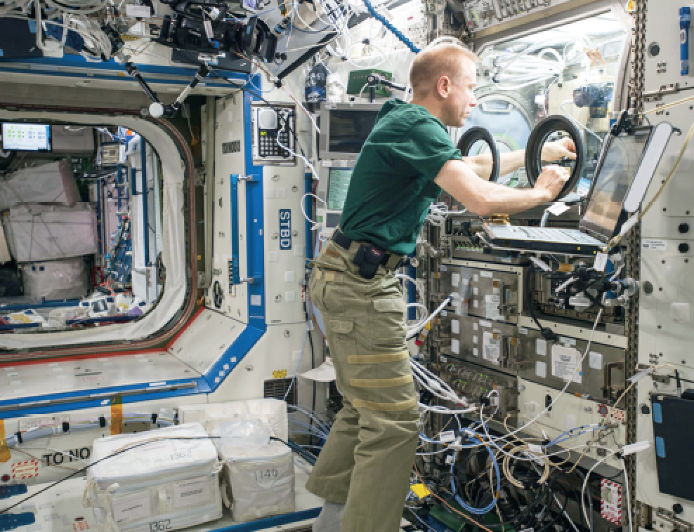
The wiring maze aboard the ISS Space Lab. Photo is courtesy of NASA.
To launch new orbital devices, one must also consider the circuit details and signal technology needed. Beyond launch RF signal management, modulated digital formats and signal aiming requires aiming and positioning beams to help maintain contact with each satellite. This helps coordinate the relative position of each satellite and working with satellite cluster management.
New programs are developing docking and repair satellites to upgrade and sustain existing orbital devices while still in space. These advanced programs add challenges to develop and sustain reserve power sources, to articulate robotic satellite collectors and provide satellite to satellite continuous communication and position control. This is today’s era of design and implementation of multiple, mixed module space electronic colonization, management and control. These military and government satellites require high reliability while exposure to external environments, ruggedized longevity, and continuous performance with
the minimum physical size, lowest weight and highest signal processing capability, storage and transmission possible.
Electronic connectors and cable systems are a serious part of that program and careful selection applied with attention to these criteria. Connectors and cable perform a large role in meeting the demands of the overall system.
At times, a combination of electrical and mechanical devices must be working together. The design engineer should pay attention to both disciplines to insure performance. Robotic arms, satellite launchers, release modules, and camera articulators operate in simultaneous mode.
One example shown in the photo is the Navy Labs and NASA proximity test system. It is used to help check out satellites while still on orbit. Connectors must handle higher amperage to operate the actuators and driver motors but also include small signal interfaces. In this case, one option is to use two separate cable and connector interconnections. Unfortunately that adds weight and consumes room for both.
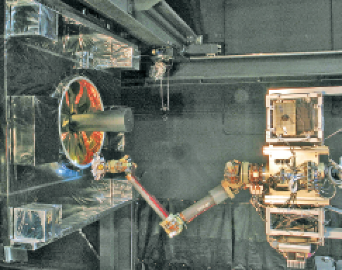
The NASA Naval Proximity tester. Photo is courtesy of NASA.
A better option is for the engineer to design a combination cable using what is called mixed-signal design. When the amperage needed for robotic motors is specified and the type of electrical signals are specified, a connection engineer can draw from proven sub-components and design an application-specific cable and connector.
This is often accomplished using a solid modeling design software that includes an inventory of each of the key connector elements using space qualified materials. The concept design model would include shape, dimensions, alignment keying, and even shielding if it is required. This model is then sent to the satellite design team for confirmation and or adjustment. Improvements include the size and weight reduction, faster design cycle and costs are significantly reduced using this method.
Finally, the design team has high assurance that the final interconnection system comes from previously tested and used components. Specialty cable is handled similarly, using both electrical and mechanical models to layout a cable that meets the applications needs. This would include cable diameter, jacket ruggedness, braided shielding if needed, and then include a wiring map of protecting each signal for noise, or crosstalk.
The power lines can still be inside the cable but isolated from the signal section. If the cable is going to handle very high speed digital signals, the cable design changes somewhat. Twisted differential pair wiring is used with separate drain wires for each high speed section.
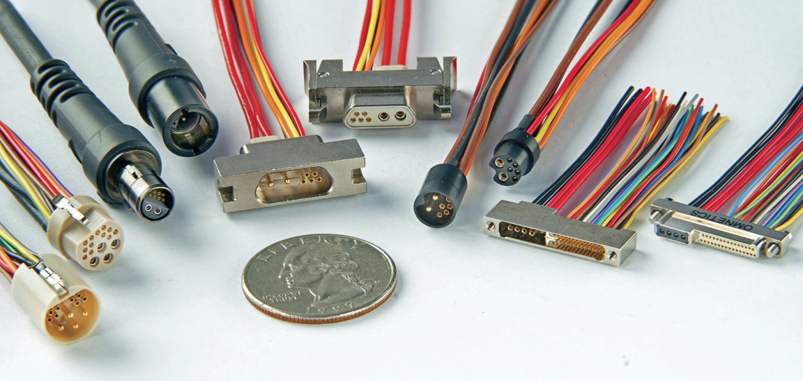
Omnetics' mixed signal connectors.
With a specified impedance to match the drive circuits, a micro or nano connector can serve over 7 Gigabits per second. Many space surveillance systems need this capability. When a high speed combination connector and cable system is assembled it can also be tested for all the basic functions before being sent to the space lab.
Final electrical tests include most basics such as impedance, insertion loss vs frequency, signal reflections, noise and jitter. More and more, critical systems also request eye-diagrams testing to help predict system performance and signal capacity.
Eye diagrams also can be simulated using spice-models based upon the elements in the cable. Experienced cable and connector design suppliers retain correlations of their simulations to save time and cost and assure performance quickly.
Initial cable and connector selection begins with a review of space qualified materials with specifications and should meet the NASA mission critical screening specification EEE-INST-002. One should include, depending on standard designs that have been tested and used in military applications, such as MIL-DTL- 83513 for micro-d connectors and MIL-DTL-32139 for Nano-d connectors.
COTs and standard connectors are a popular buzz these days by some to get connections rapidly and a lower costs. This can be a great solution, but only if the supplier has tested the materials, used low outgassing polymers and their product matches with the reliability of those
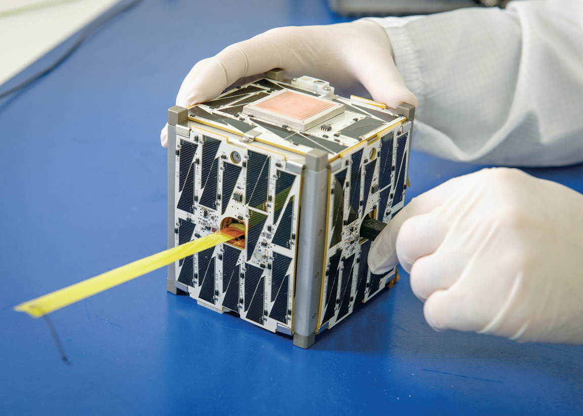
Image is courtesy of NASA.
well-defined military products.
One example in selecting a connector to last through the rigors of high shock and vibration during launch is to look at the pin and socket design system used within the connectors chosen. Selecting a pin made of tempered Beryllium Copper that is plated with nickel and gold will perform continuously without what is called fretting loss. (That is small movement in and out of the socket that rubs away the gold contact and leaves a highly resistive nickel interface. Better connectors can exceed 2,000 mates and
de-mates before wear begins to show.) Also, the connectors should interface smoothly and firmly, and have a strong key alignment control feature.
Small circular connectors are frequently used in the smaller satellites during assembly and testing. Somewhat larger connectors are more often used for routing from unit to unit or to the main power source. Larger circular connectors can also be the work horse for system to system communications within a satellite, however as voltage levels are decreasing as well as high current demand, more circular connectors are also being downsized.
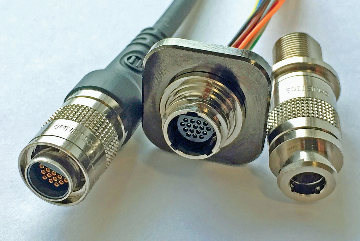
Omnetics ratchet locking circular connectors.
Mil-DTL 38999 and Micro-circular connectors can serve much of today’s new satellite systems. When necessary, this size connector can also contain 2 to 4 large pins for heaviest current loads selected for amperage ratings at space elevations. This method also helps in maintaining smaller diameter wiring and connector bulk with micro-sized pin and socket interconnects for signal processing.
Ratcheting micro-connectors are also used in robotics for highly fixable interconnects that are assembled and de-assembled quickly. The threaded couplings have metal alignment keys and insulators for quick alignment and mating, even while wearing gloves. The feel of the latching process, assures the installer that connections are positive and tightly mated. Nickel plated aluminum shells assist blind mating with first-touch alignment.
Connector contacts in space quality connectors also use military standard 83513 pin and sockets and are made of BeCu plated with mil quality nickel and gold for extended use. Metal shells and EMI shielding can be specified as well unique plating needs to prevent corrosion etc.
Coax cabling and connectors for high speed analog systems plus for broadcast transmission is another area requiring exact attention to quality of signal management as well as reliability. Designers must focus as well on what is called, the signal launch point from the transmission board to the back end of the connector and on through the connector into the cable. This is a complete study in itself and can be covered in another report.
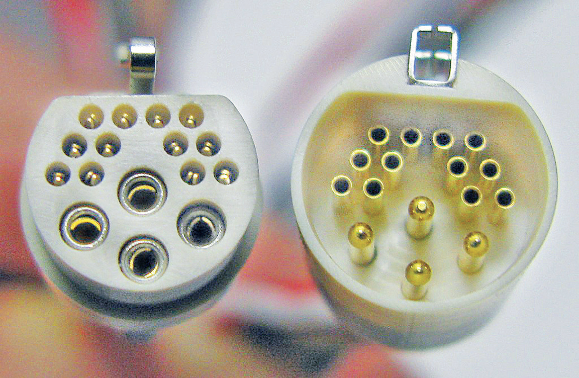
Omnetics Micro Circular Power Plus.
In conclusion; the satellite industry is expands globally, seeks to travel further and also to combine multiple satellites into a cohesive webs. We see nations pulling together and specifying space quality connectors for their satellites.
One good example is the SARah system that consists of three satellites and two ground stations. The space segment consists of two satellites equipped with the reflector technology from OHB, and a third satellite, equipped with Airbus Defence and Space’s proven phased-array technology.
The term ‘phased-array’ is used to describe phase-controlled antennas made up of numerous individual transmitter/receiver modules which can be interconnected, bundled and variably controlled. This enables direction and range of view to be adjusted without needing to move the antennas mechanically, thus providing the user with rapid image sequencing, variable image sizes and ‘blur-free’ recordings.
A key to phased array technologies, is having highest quality, multiple pin connectors for the very many output lines required to rapidly download the data generated by the antenna array system.
Satellite designers can benefit greatly from direct interface communications with their connector design source. Many have check lists made specifically for space quality connectors. There are numerous challenges that include simultaneous combinations of size reduction, lower weight, increased ruggedness, custom cable routing, and management of power in close proximity to high speed signal management.
omnetics.com/

