
Does size really matter? Perhaps satellite communications mirrors life in many ways. Bigger is more powerful. A bigger antenna means higher performance. Size, then, does matter?

Nowhere is this observed more than on huge cruise ships that sport massive radomes to secure their enormous parabolic dishes that feed streams of data to the hordes that inhabit them. Or on trailers hauled behind large trucks, in order for armies on the move to be able to assemble the largest possible antenna to provide them with as much data as their troops can consume.
Unfortunately, behind the marketing hype, the science tells us that bigger is not necessarily better. Bigger antennas only work better if they can be accurately pointed to the satellite. At higher frequencies and with bigger antennas, this challenge becomes increasingly difficult and errors much more costly — so costly, in fact, that smaller may actually be less expensive, more convenient and... better.

The Fundamentals of Antenna Size
Why do we want a big antenna?
First, for the most common case when the link is not overly impacted by uplink noise, interference or modem capability, the satellite link equation that ultimately determines the achievable throughput capability can be simplified to a very simple equation:
PR (dBW) = EIRP + GR – Lo (in dB)
which expresses the received power PR as the sum of the transmitted “Equivalent Isotropically Radiated Power” EIRP=GT PT, receiver antenna gain GR, and the free space loss or spreading loss Lo that models the impact of distance on the signal (all in dB). We want to maximize the received power PR in order to obtain the maximum signal to noise ratio at the receiver and thereby maximize the data rate that can be received. Clearly, to maximize PR , we must maximize the antenna gain G at both the receiver and transmitter.
Second, consider a transmitter antenna (the treatment of the receiver antenna is identical). The antenna gain compares the power focused in a particular direction against the power of an isotropic radiator which radiates power equally in all directions.
In the following analysis, we will look at the performance of a standard parabolic reflector because most large antennas use such dishes anyway, but bear in mind that even a flat panel antenna behaves in a similar way.
It can be shown that an isotropic antenna (which by definition has unity gain) has an effective aperture of λ2/4π where λ is the wavelength of the radiated signal. Since an antenna with gain G focuses G times more power into the same area, we can define the effective aperture of that antenna as
Ae = (λ2/4π)*10G/10 m2
or, alternatively,
G = 10log[(4π/λ2)*Ae] dB
This shows that, clearly, size matters. A larger antenna has a larger effective aperture and higher gain. A 2.4 meter diameter antenna will have a gain 5.8 times higher (7.5 dB) than a 1 meter antenna. Everything else being equal, its receive signal-to-noise ratio should also be 7.5 dB higher, and for a geostationary satellite the ‘clean’ link capacity (data rate) in most cases will then have a data rate that is between 1½ to 2½ times higher as well.
By the way, this equation shows the gain also increases as the square of the frequency (inversely with wavelength λ). In fact, the same size antenna transmitting in C-band at 6 GHz will have a gain 25 times higher (14dB) when transmitting in Ka-band at 30 GHz.
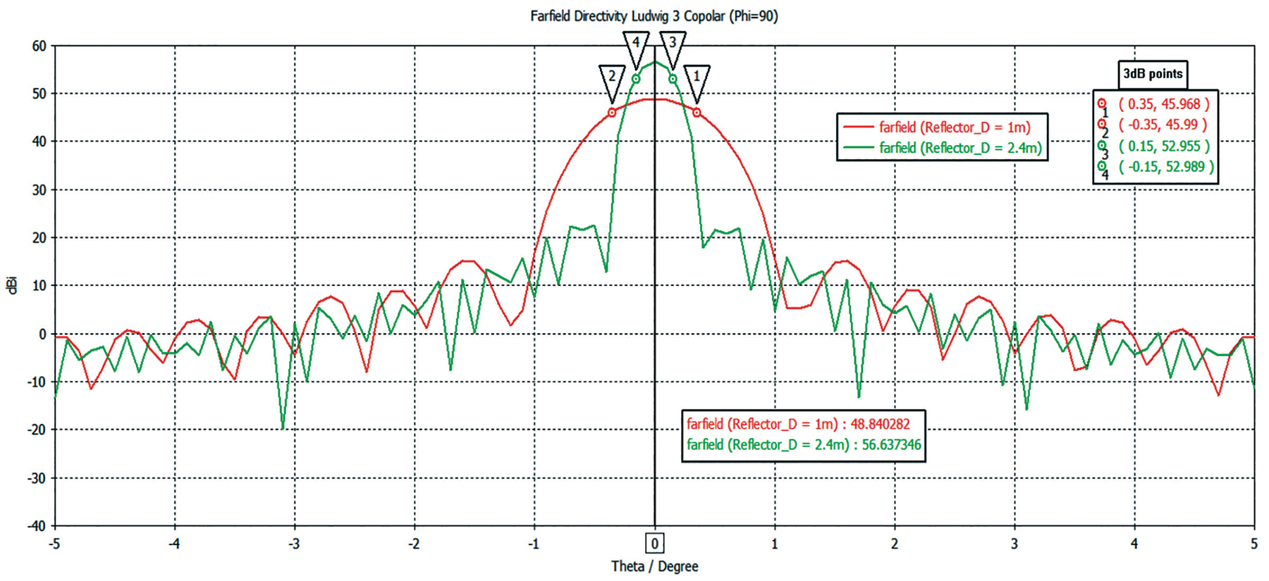
Figure 1. Transmit antenna gain patterns for a 1 meter (red) and 2.4 meter (green) parabolic antenna about boresight, with the 3-dB points at 30 GHz, indicated by markers. Click on the chart for an expanded view.
Why Bigger May Not Be Better
Marketing might want to stop there, but for better or worse, the science tells us more.
Do not forget that the antenna gain just calculated and typically quoted is the maximum antenna gain measured on boresight. Off boresight, it drops rapidly — particularly with large antennas. The total angle around boresight at which the antenna power drops by ½ (3 dB) is known as the 3-dB beamwidth. Assuming symmetry, we will deal with the angle to one-side of boresight, or the 3-dB “half” beamwidth.
Consider a conventional parabolic antenna with an aperture of D (m) operating at a frequency of F (GHz).
The 3dB “half” beamwidth angle α (measured from boresight to the 3dB point, i.e., half the conventional 3dB beamwidth) for such a dish is given by:
3dB “half” beamwidth α = +/- 11/(F*D) (deg)
Now the antenna gain as a function of small angles off-boresight with respect to the maximum gain GR on boresight is given by:
G(ф) = GR + 20log (cos (45ф/α) ) in dB
where ф is the offset angle. This is because an antenna power pattern looks like a cosine squared curve about its peak on boresight.
As an example, consider the EM Solutions maritime Cobra terminal, which has an aperture of about 1 meter in diameter.
The angle to the 3dB point is therefore (at the nominal tracking frequency of 20.7GHz)
3dB angle α = 11/20.7 = 0.5deg
The Cobra terminal uses monopulse technology to acquire and accurately track the satellite signal. It senses the satellite beacon, extracts the TE21 mode in the antenna, and uses the deep null of this signal on boresight to generate a vector to determine in which direction the antenna should point to always remain on boresight, in spite of any motion.
Typically, its TE21 monopulse tracking system will achieve an accuracy (including initial offset errors) of 50 millidegrees (0.05 deg) at 20 GHz. The drop in level of gain due to this error is therefore given by:
G(ф)/ GR = 20log (cos (45 x 0.05/0.5) ~ 0.03dB
This is negligible.
For the Tx beam at 30 GHz, the beamwidth is narrower with α around 0.35deg. The drop in power due to pointing inaccuracy is therefore higher at around 0.06 dB for the same tracking error, but this is still insignificant.
The change with gain across the beamwidth can be visualized as a function of off-boresight angle in the red curve of Figure 1, where the 3-dB gain points are indicated by markers 1 and 2.
Now consider a larger antenna of 2.4 meters. At 30 GHz, its nominal gain on boresight is 56 dB, more than 7 dB higher than the gain of the 1 meter antenna, whose gain is 49 dB.
However, the value of α is now much smaller at around 0.15 degrees at 30 GHz. The beamwidth of the latter is shown by markers 3 and 4 on the green curve in Figure 1.
If the tracking error were still 0.05 degrees, then the drop in Rx power would be ~ 0.14 dB and for Tx about 0.3 dB. These are small but now detectable in the case of the Tx beam.
However, if the tracking/pointing error was larger, say 0.25 degrees, then the Rx signal would be around 4 dB lower and the Tx signal more than 11 dB below the maximum values. This can be seen in Figure 1, where the gain from the larger antenna falls very rapidly because of its narrower beamwidth, to such an extent that its effective gain becomes significantly lower than that of the smaller antenna.
This illustrates how pointing errors can severely compromise the performance of terminals with narrow 3dB beam-widths (i.e., large antennas operating at higher frequencies). A 2.4 meter antenna mis-pointed by only 0.25 degree will perform only marginally better on receive, and significantly worse on transmit, than an accurately pointed 1 meter antenna.
Ever wonder why most data sheets for terminals do not specify the pointing accuracy? Many systems will struggle to achieve better than 0.3 degree pointing error, assuming such can even be measured.
How a 1 Meter Terminal Outperforms a 2.4 Meter Terminal
To prove the science, tests were performed on a military Ka-band transponder by a defense customer in late September of 2018 with multiple terminal types.
EM Solutions’ 1 meter Cobra terminal (Figure 2) was shown to achieve a communications data rate of 105 Mbps and to outperform competitor terminals of both 2 meter and 2.4 meter antenna diameters.
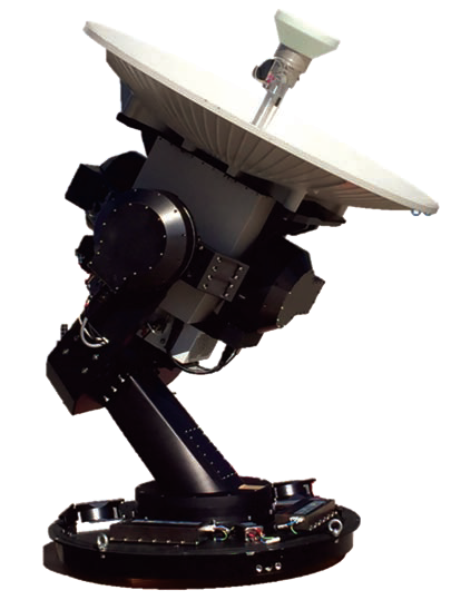
Figure 2. EM Solutions 1 meter X-/Ka-band maritime
Cobra terminal
The trials, on a spoke-and-hub network set up between capital cities in Australia and New Zealand, were to test the performance of a new military Ka-band transponder on a commercial satellite. A variety of terminals were used at the (stationary) spoke endpoints, including EM Solutions 1 meter on-the-move Cobra terminal and auto-acquire, on-the-pause 2 meter and 2.4 meter terminals from other companies.
A maximum data rate of 104 Mbps was achieved in both directions between the Cobra terminal in Brisbane and the remote network hub, surpassing the performance of terminals twice its size. That data rate was ultimately limited by the modem rather than the terminal.
These tests reveal that customers need to be careful in selecting technology aside from marketing hype. The Cobra’s outperformance was due to its superior monopulse pointing technology, which provides the most accurate tracking on boresight, whether stationary or on-the-move.
A small pointing error on a large antenna, particularly operating in Ka-band, can completely eliminate the benefit of the larger aperture. The mis-pointing error needs to be only 0.21 degrees (in military Ka-band) for a larger 2.4 meter antenna at transmit frequencies to perform no better than EM Solutions 1 meter terminal, which guarantees excellent pointing accuracy.
Poor pointing ability of actuator-controlled on-the-pause antennas or of step track on-the-move antennas is no match for the pointing and tracking ability of the monopulse technology used by EM Solutions in all its terminals.
This technology typically achieves pointing errors of less than 50 millidegrees, whether stationary or while on-the-move. That maximizes both uptime and throughput in a much smaller package than larger terminals whose marketing would lead you to believe otherwise.
The Importance of Tracking and Pointing
Whether stationary, on-the-pause, or on-the-move, the science is the same: the pointing error must be as small as possible to realize the benefits of size. Too much pointing error (0.21 degrees for a 2.4 meter antenna transmitting at Ka-band) will forgo all benefits over a 1 meter antenna if the smaller antenna is more accurately pointed.
How does the EM Solutions terminal achieve a pointing error less than 50 millidegrees, while the specification of most other terminals is probably 0.3 degrees?
Only ‘monopulse’ technology is able to maintain lock on the satellite without deliberately introducing an intentional mis-pointing error off boresight to search for the exact beam maximum, even after the satellite has been ‘acquired’.
Monopulse technology is a closed-loop system that measures the relative signal level in a higher order mode generated inside the antenna feed whenever the signal is not precisely incident along the antenna boresight.
EM Solutions uses the TE21 mode as this provides tracking information for both linear and circular polarized signals. The system uses that mode’s sharp null along boresight to derive a highly accurate corrective pointing vector to force the antenna back in line, without the need to introduce any deliberate pointing loss to determine whether the antenna is aligned for maximum receiver power, as happens with conical or step scan systems.
As a monopulse system directly measures the TE21 signal which is proportional to the deviation off-axis, such a technology also has the benefit of being able to accurately monitor and report the instantaneous pointing error to the user.
Other systems using conical scan or step-track search patterns that deliberately mispoint the system to find the maximum signal level are less accurate for several reasons.
First, they often rely on the modem to indicate the signal level and signal maximum, rather than use an integrated receiver that directly measures the beacon. Using the modem, even once it is synced, introduces lag and other system inaccuracies.
Second, to detect a meaningful signal drop across the beam requires moving off the maximum by at least 1 dB, introducing significant mis-pointing and reducing the gain.
Third, the signal level can be reduced by many other factors besides the mis-pointing, such as scintillation or fading, fooling the tracking system.
Fourth, this also means the tracking error can never be known, since the calibration between mis-pointing angle and signal level depends on a variable reference signal influenced by other factors. Using conical scan or step track to acquire and point the antenna, it is quite feasible that errors of 0.2 degrees or more persist.
Is Smaller Better?
EM Solutions has additional experience to prove the company’s point. From the firm’s network of point-to-point, terrestrial, 80 GHz, E-band radios installed over 15 km links in New Jersey, which use 1.2 meter dishes where the total 3 dB beamwidth is 0.22 degrees, we know that optical alignment of the antennas is impossible and that small movements — even due to thermal variations or wind — can cause sufficient mis-pointing to lose the link entirely.
Similarly, at Ka-band frequencies and with large dishes — even stationary ones — pointing accuracy must be within a fraction of a degree to establish a link and genuinely reap the benefits of a large antenna.
If the system must be aligned in the field, let alone on-the-move, it could be far better — for cost, performance, and size — to use a smaller monopulse pointed antenna instead of a larger one that relies on brute force alignment.
Smaller can, indeed, be better!
www.emsolutions.com.au/
Author Rowan Gilmore joined EM Solutions as a Director in 2007 and became Managing Director and CEO in October 2011. His role is to lead EM Solutions to achieve its vision to become recognized internationally as the leading designers and manufacturers of the most innovative and highest quality microwave product technology.
Rowan will be known to those in the microwave engineering community who have attended his short courses on microwave circuit design and RF wireless systems offered by Besser Associates and CEI Europe since 1990.
His previous experience includes Vice President, Engineering at Compact Software, where he introduced the world’s first harmonic balance nonlinear circuit simulator, and as Vice President, Network Services Europe for SITA-Equant, the global airline IT company, now part of France Telecom’s Orange network. Most recently he was CEO of the Australian Institute for Commercialization, where he helped numerous start-up companies and worked to accelerate technology transfer between research institutions and industry.
Rowan obtained his D.Sc. in Electrical Engineering from Washington University in St Louis. He is an adjunct professor of both Business and Electrical Engineering at the University of Queensland, and was elected a Fellow of the Academy of Technological Scientists and Engineers in 2009.