
A stroll through the exhibition hall at any of the major satellite communications conferences can seem the same, year after year. Same lights, same booths, same (bad) food, same suits.

Off-road testing in Australia
This year, one element has been different—the number of exhibitors with on-the-move terminals has doubled. At one conference, I counted at least five Chinese manufacturers, two Korean, four American, and one Australian exhibitor all offering terminals that claim to communicate with either Ku- or Ka- band satellites at high data rates on-the-move.
For good reason. Increasingly, defense forces around the world have recognized the increasing need for bandwidth, anywhere, any time. Preferably while moving. VHF and UHF radios have served on-the-move applications for years, but such radios are inherently bandwidth limited. Terrestrial microwave radios offer greater bandwidth, but require line of sight to the horizon for backhaul, and stabilized antennas to maintain pointing back to base while the node is moving.
Satellite offers a solution that provides both sufficient bandwidth and, as it is pointed skywards rather than toward the horizon, is less likely to be obscured while in motion. Fewer obstructions mean higher availability and a potentially simpler stabilization platform. Satellite communications, with higher gain antennas, also offers more protection against intercept or locating where transmissions are originating from, so is almost covert by definition.
However, “on-the-move” (OTM), or Communications-On-The-Move (COTM), can mean many things to different people—not all COTM terminals are the same. Of course, all are intended to find and keep the antenna pointing towards the fixed position of the geosynchronous satellite, independent of the platform motion.
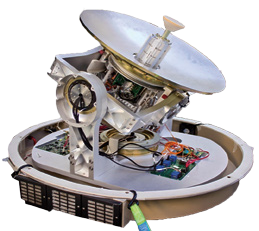
Figure 1. Ku-band off-road OTM terminal
While most will find the satellite while on-the-pause (i.e., stationary), fewer will keep pointing to the satellite when the motion becomes rough. Fewer still will be able to acquire the satellite while on the move. Others will only be able to maintain a pre-acquired pointing direction that has been achieved while stationary. Others will not be able to compensate for the sudden violent motion that can be experienced in rough sea states or off-road, and are too slow to respond to such changes. Others will take an excessively long time to recover from a blockage, as occurs frequently on land. Others have a restricted range of motion or fade when the apparent satellite position is close to the horizon.
Terminals developed for one application can often not be easily transferred to another, as for instance between maritime and airborne. For example, COM airborne applications are engineered with flat-panel antenna arrays and only avoid interference with other satellites because of the constrained nature of flight.
Defense and commercial customers are coming to realize that not all on-the-move terminals are created equal. This article describes some of the key differences that can result in either great or poor availability of the satellite link when real-world environments are encountered.
Off-road OTM Terminal System Requirements
Most high data rate SATCOM terminals operate in Ku- or Ka-band, so this article focuses only on those two bands. The majority of existing maritime terminals are still Ku-band, although demand for Ka-band variants is slowly starting to emerge.
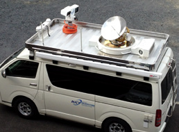
Figure 2. OTM terminal fitted to Vehicle in Japan
In the design of any satellite ground terminal, the link budget must be carefully calculated to determine the required gain (G/T) of its receiver and the effective radiated power (EIRP) of its transmitter. These two parameters, and the equivalent parameters of the satellite transponder and antenna itself, ultimately determine the mechanical and electrical characteristics of the terminal that can be developed for any application.
The first challenge to reconcile is that G/T is a variable while on-the-move, unless the antenna is mechanically repositioned to maintain a constant subtended antenna area perpendicular to the satellite boresight.
Off-road requirements for OTM terminals can be more challenging than those for maritime (in spite of the lower price expectations). An off-road terminal can be subject to more frequent and longer blockages from obstructions (particularly in the case of Ka-band frequencies, where even overhead foliage can block transmission) and more turbulent motion. The range of motion can also be greater, requiring look angles that range from the satellite being directly overhead through to the roof line, for instance in the case where the vehicle is on a steep slope. The DC power available from a vehicle can also be limited by the capability of the vehicle battery or auxiliary power system.
EM Solutions was tasked with developing an off-road, on-the-move system for use with the Japanese WINDS satellite, which operates in Ka-band at transmit frequencies around 28GHz. The basis for this was EM Solutions’ WGS-compliant terminal that also operated in the upper end of Ka-band.
Although a flat antenna with its low profile would clearly be the preferred choice, our analysis determined that there are two problems with such a choice: (a) basic physics, where the subtended (perpendicular) antenna area in the direction of the satellite determines the system gain, and is very low unless the antenna is tilted to maintain antenna gain at low look angles and (b) the radiation pattern on transmit, where a flat panel generates sidelobes off-beam as the beam is steered. Both of these issues mitigate against the low profile actually being achieved with a flat panel antenna, as to maintain high link availability at low look angles means the antenna must be tilted anyway. A phased array solution would also struggle to simultaneously demonstrate compliance with requirements for sidelobes/ESD (ITU-R S.580-6 and ITU-R S.524-9) while sharing the same physical aperture at 18GHz for receive and 28GHz for transmit.
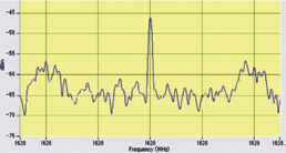
Figure 3. WINDS Telemetry Beacon
Although a cylindrical antenna somewhat lowers the profile, this has the problem of keyhole effect. This is when the satellite is directly overhead and the vehicle momentarily pitches or rolls through vertical. A cylindrical antenna with its asymmetric sidelobe pattern would be forced to rotate rapidly through 180 degrees of azimuth in order to avoid spraying surrounding satellites with unwanted emissions.
In our view, the standard, common parabolic antenna with its symmetrical radiation pattern is the only antenna that can be guaranteed to be compliant with emitted spectral density (ESD) and sidelobe interference requirements as the off-road vehicle rocks and rolls around the beam line to the satellite—and that can maintain the high gain required to ensure high link availability. A parabolic solution is also compatible with multiple bands, as the core feed structure for the solution EM Solutions has developed can be changed between Ku- and Ka-bands independently of the reflector. The solution also handles different receive and transmit frequencies relatively simply, and both circular and linear polarization.
An antenna of 650mm in diameter was selected, resulting in an antenna gain of approximately 42.5dB (including the feed and radome losses) at 28GHz. Working backwards from the link budget, it was determined that a 40W (Psat) or 20W (Plin) BUC was required to achieve the desired 54Mbps data rate. This is an exceptionally high uplink data rate to support from an OTM terminal, made possible only by the combination of high EIRP (saturated) of 58.5dBW and the unique nature of the WINDS satellite.
Unlike the WGS military satellites, the Ka-band signal in the WINDS satellite is linearly polarized, rather than circular. This is uncommon for Ka-band satellites and required a fourth rotational axis, that of the antenna feed itself, to be incorporated into the system design. The function of this fourth axis is to rotate the antenna waveguide feed so its polarization matches that of the incoming signal.
An additional control loop was fitted to monitor the polarization, as it is initially unknown and variable, and this was used to drive a fourth motor fitted within the antenna that is dedicated to rotating the waveguide feed about its axis. A similar solution is required for Ku-band terminals, as shown in Figure 1, as these signals are also typically linearly polarized.
Demonstration that the terminal could maintain a pointing error less than 0.2 degrees was required for the customer to attain a Japanese Radio License.
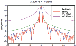
Figure 4. Plot of the theoretical and measured emitted power spectral density from the OTM antenna. The ITU and WGS specifications are shown for comparison.
Almost all OTM terminals track the satellite with a combination of INU (inertial navigation unit) and GPS compass data, using the coordinates of the satellite, the current vehicle location, and its motion to estimate the satellite direction. Such a system, in theory at least, can recover from obstructions by maintaining the pre-acquired coordinates and known motion of the vehicle to determine the optimum pointing direction, although INUs with the required accuracy and drift stability are quite costly. A further complication is that GPS compasses are susceptible to errors with off-road terminals and can cause the terminal to lose lock.
Unfortunately, with such a system, there is no way of knowing with certainty whether the antenna is correctly pointed, except by RSSI level from the modem to indicate a signal is being received. The terminal then becomes modem dependent and suffers a considerable delay in its responding to a go or no-go alarm, as the RSSI signal takes some time to calculate.
We have taken a different approach. A much more reliable method of tracking is to use the transmitted beacon from the satellite itself as an indicator of the satellite location. Such a system is then GPS immune, as GPS coordinates are only needed to hasten initial acquisition upon startup. The specifications of the associated INU can also be much looser, reducing cost.
In our system, the circularly polarized WINDS telemetry beacon was used for tracking with the WINDS terminal described earlier. However, as the platform is moving, the satellite beacon, which is used to estimate the pointing error, suffers Doppler shift. Uncertainty in the beacon frequency is consequently quite large. This is due to drift in the satellite’s own local oscillator as well as the Doppler shifts caused by vehicle motion. The frequency offset can be several hundred kHz, and the Doppler shift can change at a few kHz per second as the vehicle maneuvers. These frequency offsets must be canceled internally by the system controller.
A further challenge is that the received beacon level can be low, and the carrier/noise ratio often only a few dB. This requires careful filtering, especially digital filtering, to ensure the beacon can be recovered to a level useful enough to use for tracking. The spectrum around the beacon from the WINDS satellite is shown in Figure 3.
A mechanical approach to achieve a high level of pointing accuracy is to use a three-axis system, for azimuth, elevation, and a third cross elevation axis, to allow rotation throughout the entire sky. The additional degree of freedom in cross elevation allows direct overhead pointing to overcome the keyhole effect. As noted earlier, the keyhole effect is a major problem for systems using two-axis drives, such as those with low profile cylindrical antennas, effectively creating a blind spot directly above the vehicle.
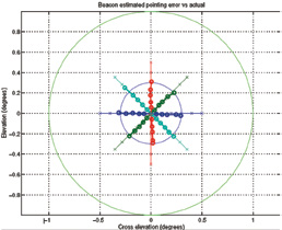
Figure 5. Monopulse Factory Verification
Adding the cross elevation axis slightly increases the height and cost of the terminal as more mechanical and control system design is required. However, this terminal vastly reduces the pointing error as the low friction cross-elevation axis allows for a much faster reaction than rotating the azimuth axis through a full half-circle would allow on its own.
Many terminals point the antenna using motors that are either geared to gimbals, or connected to them through a belt drive (similar to a fan belt in a car). Such systems are sticky and have high friction, and any vehicle motion is transferred through the drive system to the antenna, resulting in momentary mis-pointing no matter how fast the response of the control system.
Quite apart from the mechanical slack that such a system introduces into the pointing error, the bigger challenge in off-road vehicles is that angular accelerations are so extreme that, due to friction, the system recovery time is too slow to respond before the next angular shock arrives. The overall mechanical bandwidth of the motion control system must be an important consideration when matching on-the-move terminals to a vehicle, be it land, marine, or air-based.
The best way to reduce friction and achieve the highest mechanical bandwidth is to use low friction, contactless motors within the gimbals, and to position the center of gravity of the antenna, feed, and associated electronics at the intersection of the elevation and cross-elevation axes. In this way, the movable antenna system is balanced. If there were zero friction, the antenna system would not move at all – and remain pointing in the same direction – in spite of any underlying platform motion. This maximally decouples the vehicle motion from the pointing system, reducing the size of the motors needed to drive the antenna, and the power they consume, an important consideration in vehicle terminals.
Antenna Pattern I Interference To Other Operators
Measurements on the 650mm parabolic antenna conducted at EM Solutions’ outdoor antenna test range reveal that the power contained in any sidelobe is within the tight limits set by certification and regulatory authorities such as ARSTRAT (for the WGS system), or in the present case, ITU. Figure 4 shows the predicted and measured values for ESD, as well as the ITU and WGS specification limits, at an azimuthal range varying about the central beam by ±30 degrees.
The ESD is at maximum when the terminal is operated at the maximum linear power and the minimum symbol rate and is shown for the worst case condition. All measured and predicted ESD plots are referenced with respect to -12dBW/Hz at bore sight, corresponding to a symbol rate of 6Mbaud and linear power of 44dBm. Figure 4 also shows how closely the measured data follows the predicted results, subject to limitations on the step size used for ±2 degrees.
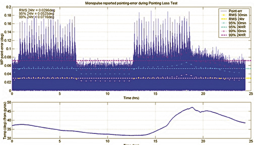
Figure 6. Measured Pointing Error Over 24 hours
Acquisition Pointing System Results— Stationary and OTM
To track the beacon emitted by the satellite to indicate its location, EM Solutions uses a “closed loop” monopulse system that is supplemented with data from MEMs gyros to point the antenna accurately.
Monopulse tracking is a radar technique that (conceptually) measures the phase difference of a signal across two closely spaced slots on the feed, on either side of the main signal path. From symmetry, the phase difference will be zero if the antenna is pointed directly towards the beacon, and the zero will be a sharp null at this point. In combination with the main signal path, which has a broader beamwidth, exceptional pointing accuracy to within a fraction of the antenna beamwidth can be achieved.
In addition, the phase difference provides a measure of how far off-boresight the antenna is pointing, as the measured phase difference across the two slots is proportional to the deviation from true boresight along the axes of the slot. The gyros are used to provide short term stabilization of the antenna, while long term stability is provided by the closed loop monopulse tracking.
Monopulse systems are, therefore, able to estimate the pointing error without any mechanical scanning and without needing to deliberately mis-point the antenna. This maximizes link gain and consequently link availability. Such also keeps the power consumption lower than most other terminals which use only RSSI as an indicator of pointing accuracy, as to find a maximum the antenna must be constantly moved off maximum (in an intentional conical scan) to be certain the antenna was indeed centered around a maximum. With a monopulse technique, the antenna is held stationary rather than intentionally swept in a constant scanning motion.
Nearly all other OTM terminals are “open loop,” since their sole control mechanism is through calculation using GPS and INU data that is unrelated to feedback from the satellite itself. The closed loop system described here, using monopulse, can provide pointing error measurements that can be used to derive the pointing loss for certification purposes.
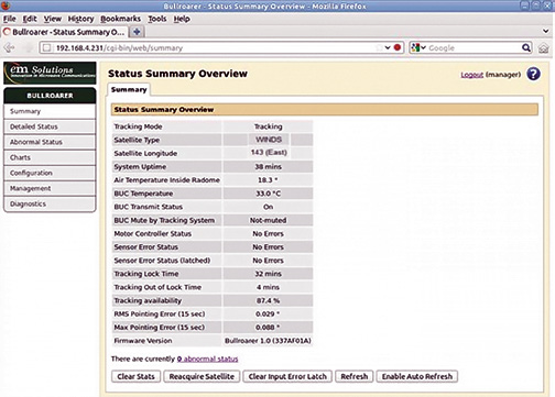
Figure 7. OTM GUI Reported Pointing Loss
This method of measuring pointing loss is not affected by scintillation, which can corrupt pointing loss calculations based on spectrum analyzer measurements of beacon levels.
Figure 5 shows a verification graph of the actual errors introduced in the OTM terminal by manually driving the terminal off boresight and measuring the displacement with the encoders on the terminal. This can then be compared to errors as measured by the monopulse feed. There is excellent correlation between these two measurements which can provide evidence of achieving a nominated pointing loss.
Pointing error plots such as those in Figure 6 can then be produced by the monopulse closed loop tracking system in the field. The motion shown here was generated by a 6 degree-of-freedom motion table to simulate both off- and on-road conditions. Tests were performed over 24 hour periods and the motion was divided into 4 x 6 hour blocks consisting of 6 hours motion, 6 hour no motion (static), 6 hours of motion and 6 hours static.
The 6 hours of motion was further divided into 6 x 1 hour cycles. Each 1 hour cycle consisting of 15min of static, 15min of sealed road, 15min of unimproved road and 15 min of off road motion.
The diurnal temperature variation is also shown in the lower graph of Figure 6 for reference purposes.
The measured pointing loss shows a maximum of no more than 0.2 degrees off-boresight over 24 hours.
The OTM terminal includes a web-based GUI that reports on the status of critical indicators. Figure 7 above presents the summary page reported by the terminal. As can be seen, the terminal will provide both the maximum pointing error and RMS pointing error calculation as part of the GUI for the user to monitor in real time.
Recovery After Blockage
Off-road terrain can be unique for its violent motion and also for path interference susceptibility from overhead foliage or man-made structures. Recovery after such blocking is an important consideration.
Testing for performance off-road should involve:
• Off- road testing
Such a test includes turns, stops, varying road conditions, and higher speed travel, checking for pointing error.
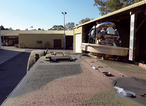
Figure 9. Acceptance testing on a military vehicle.
• On-the-move tracking
This test involves acquiring the beacon while stationary, then driving through short to medium duration obstructions, such as trees, while staying on the move.
• On-the-move acquisition
This test entails staying in an obstruction for a longer period, perhaps two minutes, then driving out of it and staying on the move. The terminal must reacquire while in motion.
• Stationary obstruction
In this test, the vehicle is parked in front of an obstruction for several minutes, then moved out of the obstruction to test for reacquisition.
• Cold starts
The acquisition time from a cold start is measured, both stationary and while on-the-move.
Achieving satisfactory outcomes requires a good understanding of the terminal motion control system and its dynamics. Careful attention must also be paid to the INU gyro control loop, and the satellite heading and elevation calculations, as these are used within a higher bandwidth motion control loop. Monopulse tracking achieves unparalleled accuracy (less than 0.2 degree error) in all off-road tests, and reacquisition of the beacon in 20 seconds (on average) while moving, after being in obstruction for 2 minutes, and never failing to reacquire on-the-move, even while turning.
GPS Immunity
GPS independence is important for military communications due to the possibility of local jamming. INU open loop pointing requires heading information and constant GPS updates to prevent gyro drift and is therefore vulnerable to GPS attack. The EM Solutions OTM terminal is immune from such attacks as it does not require GPS for acquisition, tracking or polarization adjustments.
Acquisition
During acquisition, the terminal’s position on Earth is required to calculate a look angle for its initial search, but in the absence of GPS data, this can be entered manually. The terminal’s inexpensive and ITAR-free INU and gyros do not require a GPS input.
Tracking
Closed loop beacon tracking clearly does not require any GPS data as the monopulse feed maintains pointing accuracy better than 0.2 degrees on its own.
Polarization
GPS compasses are often used to provide heading information required for polarization corrections when tracking with OTM terminals. GPS compasses work well in the maritime or aviation environment where there are relatively few obstructions. However, in the land environment, their operation is inhibited by regular obstructions or multipath caused by nearby objects causing the compass to ‘unlock’ and provide no heading information. Subsequent ‘lock’ time can be in the order of minutes even in clear sky conditions.
In place of a GPS compass, EM Solutions uses the data obtained by tracking the satellite combined with its approximate position on Earth and a proprietary algorithm to calculate the correct polarization.
These features provide GPS immunity to the terminal and have been incorporated to provide similar functionality to the original terminal developed for the Australian Defense Forces.
Data Rates OTM
The terminals were fitted to mobile communication nodes and OTM testing conducted by the customer in Japan over the WINDS satellite. The data rates of 54Mbps uplink and 155Mbps downlink were confirmed while on the move.
Conclusion
Many terminals lay claim to operating “on-the-move.” Few are suited to off-road conditions, where high frequency vibrations in all three axes makes acquisition on-the-move and reacquisition after obstruction slow at best, and impossible at worst.
This article has described a family of terminals that have been developed to track the satellite using a closed-loop tracking system that relies on a signal from the satellite itself for its direction, rather than an outside source. Such a system, using a monopulse technique, is able to achieve sub-degree pointing accuracy that maintains the highest possible link margin and link availability of any system.
Broadband on-the-move satellite communications terminals of this type now offer true mobility and high data throughputs to military users and first responders, even under the most demanding and severe on-the-move conditions experienced off-road. The support of our partner Jepico and NICT Japan in developing the terminal described in this article is greatly appreciated.

There’s additional information at the EM Solutions infosite: http://www.emsolutions.com.au/
About the author
Rowan Gilmore joined EM Solutions as a Director in 2007 and became Managing Director and CEO in October 2011. His role is to lead EM Solutions to achieve its vision to become a world-leading company recognized for offering technologically superior microwave modules and systems for next generation broadband communications.