
Broadband communications anywhere, anytime, anyplace can only be provided by satellite communications.

However, when communications are mission-critical, how can they be made more assured, resilient, and resistant to hostile or environmental interference?
Interference mitigation through exacting terminal design against the effects of weather, satellite congestion, frequency jamming, and motion itself all add toward this objective.
In fact, assured communications is similar to an onion with numerous protective layers in its skin. Those layers include maximizing link availability through good design, use of redundancy, frequency stealth, coding, limiting radio emissions in unwanted directions, and protection against interferers.
These are particularly difficult to achieve with satellite communications while on the move, but often it is while on the “run” that communications is most critical.
Consider each layer. First, improving link availability by maximizing the link budget is a good place to start. The link budget determines the allowable fade margin, which can be maximized by using the highest power transmitters possible, most sensitive receivers, steered antennas to maintain maximum antenna gain, and best pointing accuracy to minimize pointing loss.
Time on satellite is probably the biggest contributor to the availability equation: minimizing the time for a SOTM terminal to acquire or reacquire the satellite is critical, as is maintaining that link during violent motion conditions.
Second, redundancy can be improved in satellite communications through the use of multiple transmitters, as Block Up Converters (BUCs) are usually the most failure prone component in the link. The use of multiple satellite systems also assists with this need.
Frequency stealth might entail switching or spreading either the modem output frequency or the RF frequency. Changing to a lower frequency band can also protect against weather effects that can cause loss of the satellite link at the higher Ka-band frequencies.
Third, coding and other security precautions, such as encryption at the data layer, can protect against theft of data.
Fourth, ensuring that the radio signal is highly directional with minimal RF spillover or sidelobes and protecting against interfering signals through careful electromagnetic design and analysis, is required and will avoid ‘theft’ of signals or intrusion upon the radio layer.
Such signals can also be unintentional or non-hostile but still cause link failure—for example, nearby radar systems often result in a total loss of communication capabilities.
This article will initially cover the basic parameters that determine the link budget and then describe how such features can be engineered into a highly assured and robust terminal with almost no increase in the total cost of ownership when compared to lower cost platforms.

An Australian Cape Class ship that defends the nation's coastline.
Maximizing The Link Budget
Shannon’s famous equation gives the maximum capacity C of a general communications channel in bits per second as C= B log2 (1+NSR) where B is the used transponder bandwidth in Hz and SNR is the signal to noise ratio at the receiver.
Of course, B also determines the receiver noise, so SNR varies inversely proportional to B, thus maximum capacity does not always increase linearly with bandwidth. However, for typical values of SNR achieved at a ground satellite terminal (1 < SNR < 20), Shannon’s equations tells us that if the signal power drops by half, the bandwidth needs to double to maintain roughly the same capacity C.
In their excellent paper [1], Murthy and Svesko point out the impact that a reduction in signal level can have. Noting that if the ground terminal EIRP is backed off by 3 dB (in their example, to prevent inter-satellite interference due to a pointing error of 0.5 degree in the terminal), the bandwidth needed to maintain the same bit rate doubles, and consequently the cost to lease the increased bandwidth.
Although rarely specified by a customer, total cost-of-ownership (TCO) for a communications network should be a critical determinant in the selection process for an on-the-move or on-the-pause antenna terminal.
In their example outlined in [1], even if a terminal with more accurate pointing error ( <0.2 degree) costs $100k rather than $50k for a less accurate terminal, after approximately six years of operation the terminal with the higher initial procurement cost will be a more cost effective network solution.
Any reduction in link gain impacts TCO in exactly the same way. The simplest expression for the link equation for a one way satellite link (in dBW) is PR (dBW) =EIRP+GR–L0 where PR is the received power, GR is the receive end antenna gain, EIRP is the Equivalent Isotropically Radiated Power (equal to GTPT ) of the transmitter, and Lo the one way channel and spreading loss.
For a geostationary satellite, the spreading loss component of Lo is 201.5 dB in X-band, 206.5 dB in Ku-band and 213 dB in Ka-band on the uplink. Therefore, PR normally ends up quite close to the receiver noise floor so any increase in Lo (for instance, through poor pointing or rain attenuation) or any reduction in terminal GR (or GT, i.e., EIRP if transmitting) can cause the received signal power to drop below threshold, and the link will be lost or at best, severely degraded. GR is determined by the size of the antenna and, in the case of flat panel antennas, the angle of incidence as well, losing 3 dB at 45 degrees orientation from normal.
As Shannon’s equation highlights, such a drop of 3 dB in PR causes either the bit rate to halve (eventually forcing it to zero), or requires the bandwidth (and cost) to double to maintain the same capacity.
Of course, TCO is secondary when assured communications are at stake, but it is interesting that the same measures that improve link availability (and assist with assured communications) can also reduce the total cost of ownership, all other elements (such as link capacity) being equal.
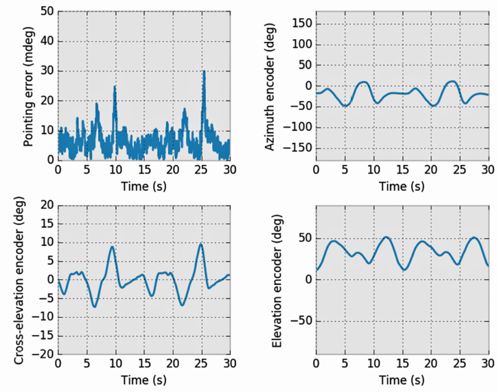
Figure 1. A sea-state motion profile, measured by cross-elevation, azimuth, and elevation angle deviations (degrees) in time, and the resulting stabilized terminal pointing error (millidegrees, top left)
As just described, both the gain and pointing performance of a SATCOM antenna system are important in preserving link availability. In [1], pointing performance is defined by the unit’s ability to keep the antenna boresight pointed directly to the satellite during operation. However, it is more than that—performance also relates to the time taken to initially acquire the satellite.
For SOTM applications, these requirements are challenging due to the complex engineering required to steer the antenna’s transmit beam directly to the satellite with high availability during vehicle motion. Only ‘monopulse’ technology is able to maintain lock on the satellite without deliberately introducing an intentional mis-pointing error off boresight to search for the beam maximum.
Monopulse technology is a closed-loop system that measures the relative level in a higher order mode in the antenna feed, typically the TE21 mode from the satellite signal. The system uses that mode’s sharp null along boresight to derive a very accurate corrective pointing vector to force the antenna back in line, without the need to introduce any deliberate pointing loss to determine whether the antenna is aligned for maximum receiver power, as happens with conical or step scan systems.
As a monopulse system directly measures the TE21 signal which is proportional to the deviation off-axis, such a technology also has the benefit of being able to accurately monitor and report the instantaneous pointing error to the user. This ensures the BUC is only muted when the antenna is confirmed as being off-axis, rather than, for instance, if the received beam is measured as temporarily weak, such as due to a passing cloud.
Figure 1 shows the total pointing error off boresight in millidegrees experienced by EM Solutions’ new Cobra terminal in severe sea state conditions, where a closed-loop monopulse system stabilizes the system and compensates for the ship’s motion.
The underlying motion is recorded by the terminal’s three angle encoders in the base of the terminal, in the angular directions of azimuth, elevation, and cross-elevation, all in degrees.
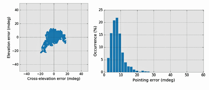
Figure 2a (left). A typical polar plot of the pointing error as measured by deviation from true boresight in elevation and cross-elevation angles (millidegree) vs. time.
Figure 2b (right). The total pointing error experienced by the terminal plotted as a histogram over all time samples. Note that the pointing error rarely exceeds 20 millidegrees
Figure 2a shows the total pointing error as a polar plot in the elevation and cross-elevation directions vs time, while Figure 2b shows the same data as a histogram.
The pointing error is maintained at less than 10 millidegrees for 75 percent of the time, and to less than 20 millidegrees for 97 percent of the time, subtracting almost nothing from the link budget. This is comfortably less than the maximum pointing error of 200 millidegrees specification on the WGS constellation.
Furthermore, the monopulse system and motion algorithms used to acquire the link and re-establish it after blockage result in tracking performance that has been reported by customers to be the best in the industry. All these features, together with a steered parabolic antenna that always gives maximum gain irrespective of pointing direction, ensure the link equation is optimally tuned for maximum uplink time, availability and link capacity.
Redundancy
However, there is still more that can be done to assure satellite communications. Redundancy in hardware, frequency and satellite selection are three additional ways to introduce resilience into the link. The choice of satellites and use of multiple bands mitigate against weather effects, jammers, interferers, congestion, and even the loss of a satellite.
The approach taken at EM Solutions is to engineer a satellite terminal that automatically switches between any of three satellite bands on different satellites, even while on-the-move. Although maritime terminals already exist with either commercial or military Ka-band capability, or with dual X-band and military Ka-band capability, none offer universal on-the-move capability (on land or sea) in a convenient size package, simultaneously operating in both X- and Ka-bands, or with fall back to commercial Ka-band on demand.
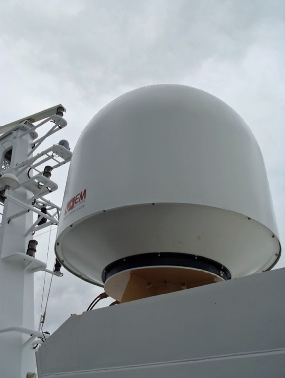
Figure 3. The first of the Ka-multiband terminals on board an Australian Border Force vessel.
This requires the use of separate BUCs for X-band and Ka-band, but this is beneficial since the pair then adds increased hardware redundancy on top of the improved link redundancy. Such a combination brings the benefits of assured communications whenever a satellite is visible without manual changeover of hardware.
Assured Communications
The EM Solutions team’s approach in developing an assured satellite communications on-the-move terminal has been to work closely with the customer, represented by the Australian Defence Science and Technology Group (DST), to understand their requirements, and cooperate with several collaboration partners. These included Inmarsat Global Government, who provided support during the type approval process, and Intellian, who modified their GX modem and below deck unit to pass signal control information between the Inmarsat Operations Centre and the EM Solutions transmitter equipment and stabilized platform.
The design was based on EM Solutions latest generation military Ka-band Taipan class COTM (Communication-On-The-Move) terminal, in which pointing using monopulse beacon tracking was first perfected. However, that system was land based and with its squat profile did not give the negative elevation angles required from a maritime terminal to compensate for ship roll below the horizon.
Using the same powerful direct-drive brushless motors, balanced three-axis gimbal design, and a new “Cobra” style pedestal offering greater elevation range, the new system provided minimum mechanical play and thus maximum position accuracy in a very robust and strong platform. The monopulse pointing system and tracking algorithms were ported and tuned to the new pedestal and proved to be extremely fast and accurate, equally capable of maintaining the link in rough sea profiles as they had off-road.
Now type approved for Inmarsat GX and operational on Cape Class ships defending Australia’s coastline (Figure 3), the Cobra-class terminals are providing—for the first time—broadband services to the crew, capable of using either the military or commercial bands—the choice depends on satellite availability and network congestion. Simultaneous operation on both X- and Ka-bands has also been tested on the military payload of the Optus C1 satellite, with WGS certification being the next step.
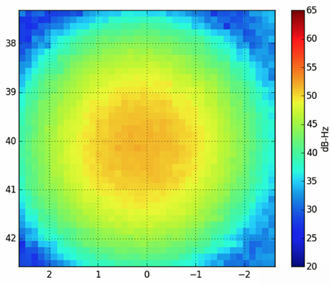
Figure 4. A typical “heat map” produced by the terminal, showing the C/No of the received signal (measured in X-band, right axis) plotted against elevation angle (Y-axis) and crosselevation angle (X-axis
The greatest innovation in the latest Cobra X/Ka-multiband terminal is the antenna feed system. Optimized for its electromagnetics, the system generates antenna pointing vectors from both the X-and Ka-band beacons of the WGS satellite and communicates in the traditional manner at Ka-band, all the time supporting simultaneous communications on the satellite’s X-band transponder, whenever required to protect against rain fade or to provide added capacity.
In addition, the system can then fall back to tracking and operating on the alternative Inmarsat GX satellite system in the case of congestion or for operational reasons.
When to do so can be determined manually or by monitoring the receiver carrier to noise ratio. Figure 4 is one of the calibration plots the system can generate, and shows the signal’s carrier to noise density level around boresight.
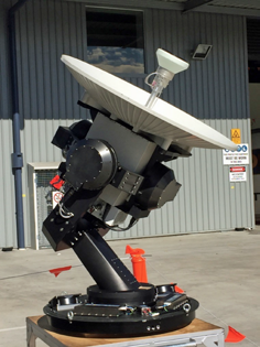
Figure 5. Under the cover — the Cobra multiband X-/Ka- terminal in test at the EM Solutions fact
This particular plot shows that a pointing error of 1 degree would result in a 3 dB reduction in signal power from 52 to 49 dB Hz. Clearly, useful assumptions about the cause of a reduction in signal level can only be made if pointing error can be ruled out as a possible cause, as can be done with this system.
Using a 1 meter diameter parabolic reflector, the terminal has a footprint of only 0.75 meters and can be deployed on a range of vessels, from small patrol boats to large ships. At the same time, re-engineering efforts have been applied to reduce cost, top weight, and overall terminal volume consistent with the other operating constraints. The newly developed terminal shown in Figure 5 meets both WGS and Inmarsat specifications. Compared with older terminals, the benefits of the new Cobra multiband terminal include:
• Network survivability with assured communications in a contested environment
• Rapid and automatic self-healing in the event of rain fade or other link outage by switching satellites or frequency band
• Fully transportable and operational on-the-move capability with unparalleled satellite tracking capability in three bands across all ranges and types of motion (land or sea)
• Support for broadband communications (data rates up to several Mbps) without using excessive satellite transponder resources that would be consumed by a very small terminal
• Fall-back to a fully integrated commercial capacity in the event of failure or congestion of the military network
• Configurability for a range of platforms to suit either a small or medium vehicle or vessel, with simplified field repair and cost optimization
• Universal stabilization to the most severe motion conditions, i.e., the terminal can be used either on land or at sea
• All X-band and Ka-band electronics are integrated within the radome in a single RF “can", avoiding the need for expensive and lossy waveguide runs to external equipment racks, and simplifying maintenance
No longer a pipe dream, high availability SATCOM is now available in a single terminal whose total cost of ownership is no greater than conventional single-band, non-redundant terminals.
EM Solutions roadmap includes extending the system to Ku-band and to airborne platforms for even more versatility—watch
this space...
www.emsolutions.com.au/
Reference
[1] SOTM & SOTP: Satisfying VMES, Rohit Murthy and David Svesko, General Dynamics Mission Systems, MilsatMagazine Jul/Aug 2016,
pp. 32-35
-