
A significant cost of AISR missions today is the leasing of bandwidth from commercial satellite (COMSAT) systems, including
Ku-band. Going forward, DoD guidance recommends future AISR systems support both commercial Ku-band systems (legacy and future), as well as military Ka- band [1].
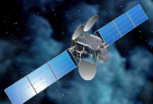
Artistic rendition of the Intelsat 34 satellite. Image is courtesy of Intelsat.
In this whitepaper, we analyze and predict AISR performance on the Intelsat EpicNG satellite constellation, with comparisons to legacy Ku-band and Ka-band systems. EpicNG is Intelsat’s next generation satellite platform that delivers global high-throughput technology without sacrificing user control of service elements and hardware. The EpicNG platform uses C-, Ku- and Ka-bands, wide beams, spot beams, and frequency re-use technology to provide a host of customer-centric benefits.
This article provides an overview of the Intelsat EpicNG satellite system, including performance data, description of AISR missions, systems and waveforms to be used in the analysis as well as link budget analysis that predicts the performance of EpicNG with comparisons to legacy Ku- and Military Ka-band.
Intelsat EpicNG
Architecture
Intelsat EpicNG is a series of multi-spot, high frequency re- use satellites [2]. The satellite beams are commonly referred to as User, Gateway, Wide or Spot beams.
User and Wide beams use standard Ku-band frequencies. Gateway and Spot beams use C-band and alternative frequencies. Global Ka- band beams are also provided. The frequency diversity between User/Wide and Gateway/Spot beams maximizes beam coverages and bandwidth. The diversity allows placement of Gateway/Spot beams co-incident with User/Wide beams without impacting the bandwidth available in any of the beams.
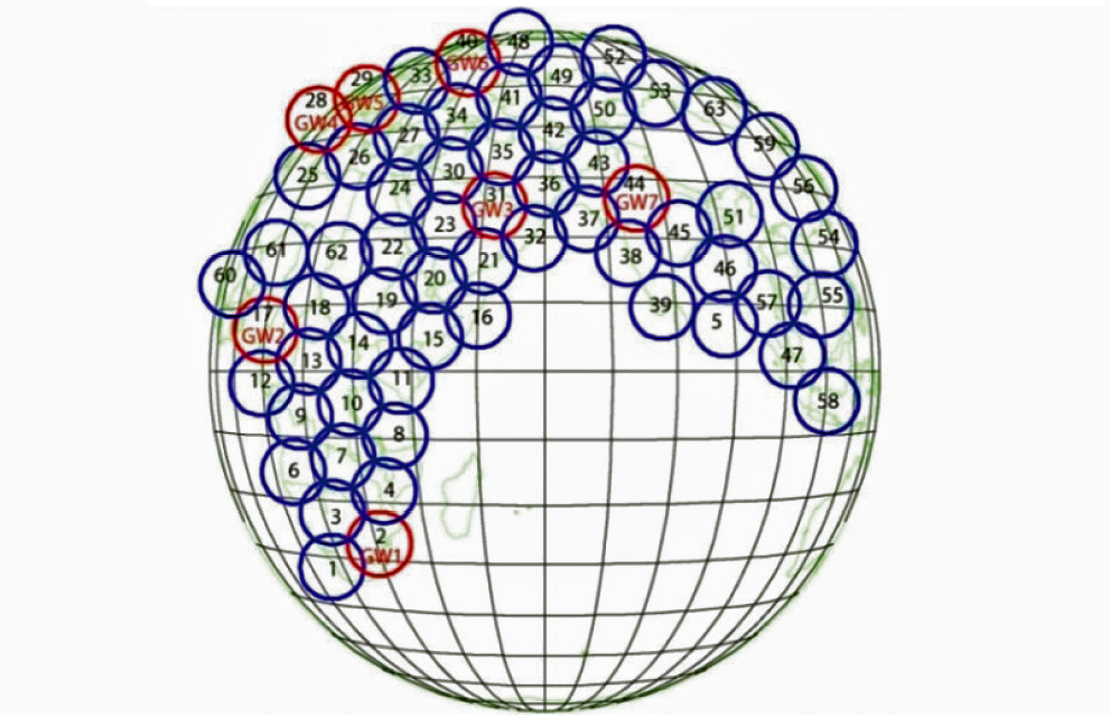
Figure 1. IS-33e Ku-band User & Gatweay Beams.
Gateway/Spot beams do not have fixed connectivities to/from User/Wide beams. Via an on-board digital switch, any uplink beam, User, Wide, Gateway or Spot can be connected to any downlink beam, User, Wide, Gateway or Spot. All beam connectivity permutations are supported, including loopback. Gateway and Spot beams can be viewed as high capacity beams providing connectivity to any User or Wide beam as required.
User and Wide beams are primarily designed for use by remote terminals while Gateway beams are primarily designed for use by hub / teleport ground equipment. Although beams are tailored for expected usage, all terminal types—hub, controller, remote, etc.—can be operated in all beam types. Beam layouts for IS-33e are shown in Figures 1, 2 and 3.
Beam to beam connectivities can be established in multiple sub-bands within the transponder’s bandwidth. A beam may have multiple
simultaneous connectivities.
As an example, User beam #7 may have 26 MHz loopback, 26 MHz to/from Gateway #1, 13 MHz to/from Gateway #2, 13 MHz to/from another User beam, and so on. Satellite operating procedures and tools are under development with the expectation that beam connectivities will change over the life of the satellite to match evolving demands.
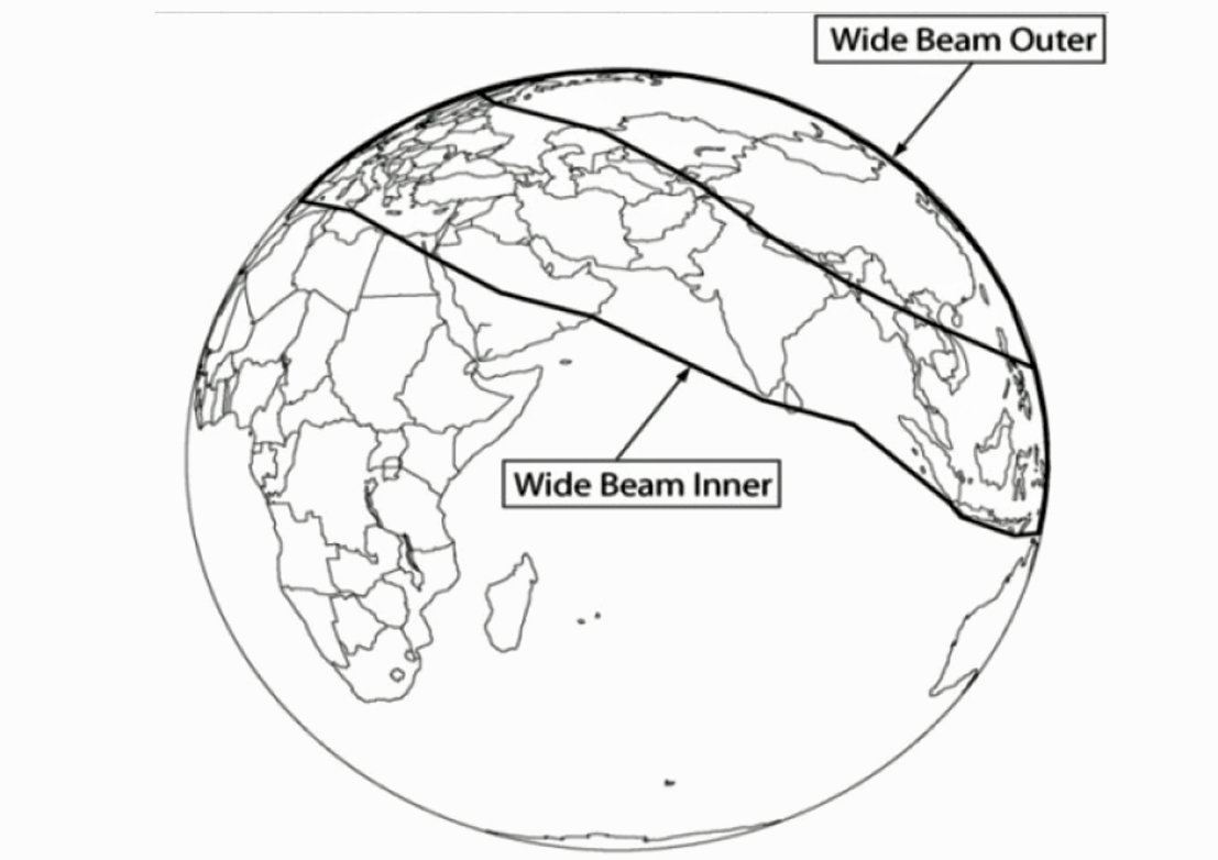
Figure 2: IS-33e Ku-band Wide Beam.
User beam frequencies and polarizations are selected to maximize beam-to-beam isolation. Better beam isolation translates into improved received signal-to-noise ratio (SNR) and corresponding higher satellite efficiency in terms of megabits per second (Mbps) transmitted per megahertz (MHz) of satellite resource.
Based upon known and expected demands, some User beams are allocated bandwidth different from nominal. To date, all beams on Intelsat EpicNG satellites are of fixed location. Steerable beams have been, and will continue to be, considered.
EpicNG supports open architecture. Users can deploy ground platforms of their choosing, in their desired network topology (e.g., star, mesh, distributed star), across the beam connectivities already described.
Open architecture also allows Users to select the data rates supported and whether their network capacity operates in a dedicated or shared manner.
Ku-band was chosen for the User beams for multiple reasons:

Figure 3: IS-33e C-band Spot Beams.
• Large deployed base of Ku-band terminals requiring ongoing support and improved performance
• Compatibility with traditional, wide beam, Ku-band satellites to enable terminals to operate across multiple satellite platforms.
• Better performance than Ka-band during rain
• Better performance than Ka-band when utilizing equal- sized spot beams [3].
Future EpicNG satellites may have Ka-band User beams if market demand demonstrates the need.
The multi-spot, high frequency, re-use design provides inherent interference/jamming mitigation. An intentional or unintentional jammer must be within a beam to interfere. If outside the beam, the satellite’s sharp beam roll-off design will provide isolation.
Additionally, beams operating in cross connect (e.g., User to Gateway) provide a lower probability of detection. Transmissions within a beam are not seen in the uplink beam but rather at the geographically distant cross connect beam. This split beam operation also enables transmissions into a User beam while adversaries are attempting to jam transmissions from the User beam.
The onboard digital switch provides another layer of interference protection. When interference is detected, the onboard switch can be configured to not propagate the interferer further. The interferer can be terminated in the satellite or it can be switched to a beam and frequencies specifically established for monitoring. As that is being done, the desired transmitter’s carrier can be tuned to uplink in clear bandwidth and, via the switch, be downlinked at its original intended frequency.
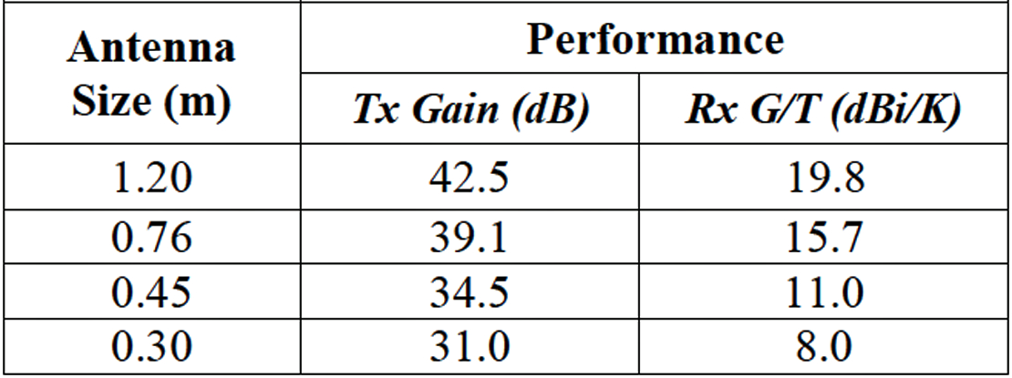
Table I. Remote Terminal Parameter
Finally, in terms of protection, wider transponder bandwidths support a greater range of protected waveforms and provide greater protection performance. EpicNG User beam transponders are nominally wider than the 36, 54 or 72 MHz typical on legacy Ku-band satellites and the 32 MHz wide transponders on Inmarsat I-5 Global Service Beams [4].
Intelsat’s EpicNG satellites are designed as a complementary overlay to Intelsat’s existing fixed satellite network. They are not intended to replace wide beam satellites but rather augment where high capacity and high performance are needed.
EpicNG will be fully integrated into Intelsat’s existing satellite fleet and global IntelsatOne terrestrial network. To date, commitments have been made for seven EpicNG-class satellites and more are in planning stages. Intelsat continually evaluates and updates its fleet replenishment and enhancement strategy. EpicNG-class satellites are an integral tool in that process.
Legacy Ku-Band Comparison
Nominal beam edge EIRP for a User beam on an EpicNG-class satellite is 55 dBW. This compares to 53 dBW beam peak performance for legacy Ku-spot beams on IS-IX series satellites. Beam peak on EpicNG User beams is nominally 4 dB over beam edge, or 59 dBW. In other words, over the entire EpicNG User beam coverage area, satellite EIRP will match or exceed that provided at beam peak on legacy IS-IX Ku-band spot beams.
Intelsat EpicNG G/T performance, similar to EIRP, compares to, or exceeds, beam peak performance of legacy satellites; across the entire User beam coverage area. Legacy IS-IX Ku-spot beams nominally provide 9dB/K G/T at beam peak. EpicNG User beams provide 8dB/K G/T at beam edge and 13dB/K at beam peak.
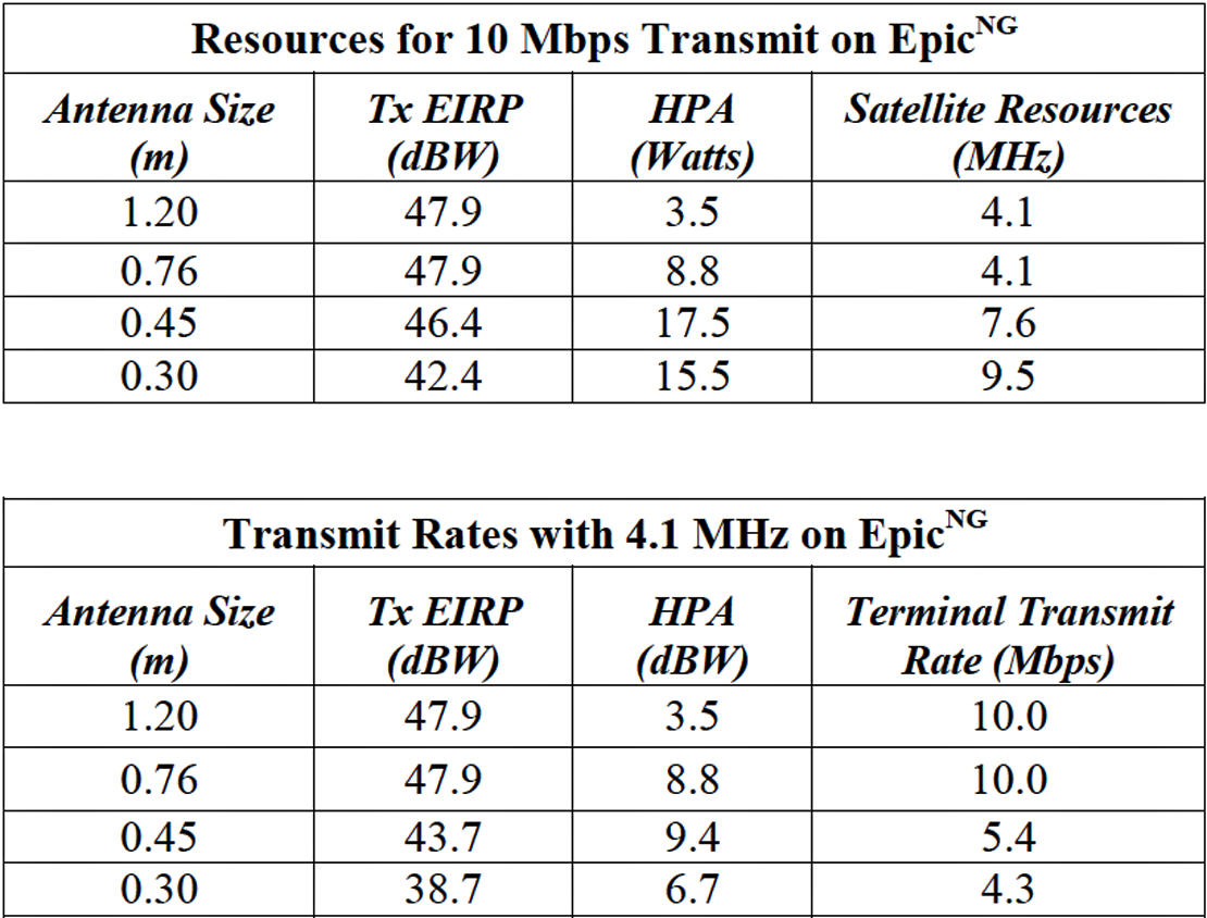
Table II. AISR Terminal Performance On Intelsat Epic NG.
Application To AISR
AISR missions are often required to use smaller, so-called disadvantaged, satellite terminals. This need is driven by size, weight and power (SWaP) and other operational constraints. The high EIRP and G/T performance provided by Intelsat EpicNG satellites are very advantageous for these smaller terminals.
The higher G/T provided by EpicNG-class satellites translates into higher transmission rates from existing terminals and/or less terminal EIRP per transmitted Mbps. An interesting phenomenon occurs due to EpicNG’s high EIRP values. If a User beam transponder is operated at saturation with the power distributed evenly across the available bandwidth, typical inter-satellite coordination limits would be exceeded; i.e., Intelsat EpicNG’s downlink power spectral (PSD) would be excessive. EpicNG, of course, will not operate in such a manner.
AISR Systems + Technology
AISR satellite networks are typically characterized by high-throughput return links (remote to hub) and lower throughput forward links (hub to remote). This network architecture is opposite the more conventional Internet/surfing or video distribution models. Consequently, SATCOM engineering for AISR systems requires special considerations, especially for the return link.
Return link data rates of interest range from 1 to 20 Mbps for most systems, with 10 Mbps being of particular interest, as it allows transport of high-definition full motion video, HD 720p, along with other platform/mission traffic. AISR systems can be reasonably divided into manned and unmanned variants.
Manned AISR Systems
Manned AISR systems are typically commercial airframe systems with special equipment sets supporting the ISR collection and dissemination. The airframe often limits the antenna size. 30 to 45 cm diameter, reflector-based, antennas are common for smaller platforms such as Gulfstream and King Air.
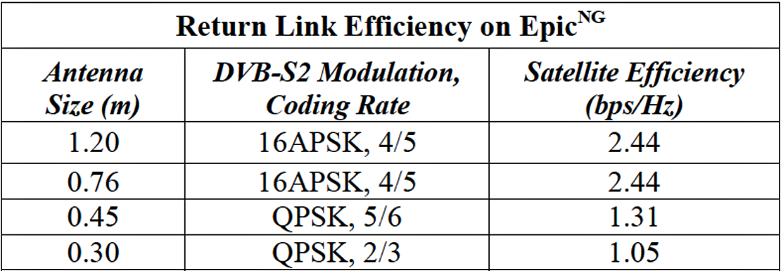
Table III. Intelsat Epic NG Efficiency With 7.3 Meter Hub
Larger airframe platforms can support up to 1 meter antennas and low-profile, phased-array antennas are common. Manned systems often have larger forward link throughput requirements, as traffic includes both ISR data as well as other IP-based services, including voice and data.
Unmanned AISR Systems
A variety of countries maintain fleets of unmanned AISR systems. For the US DoD inventory, satellite capabilities are common on Tier III and IV UAS [5] with 30 centimeters up to 1.2 meter diameter antennas being common.
Example terminals include the L-3 Communications Ku-band SATCOM data link Predator Reconnaissance System [6]. Return link data traffic is typically sensor data, including Full Motion Video (FMV), while forward traffic is primarily platform command/control. Future sensors and missions will demand more return link throughput, at lower costs. Migration to align with future COMSAT architectures is critical [5].
AISR Waveforms
A variety of AISR SATCOM waveforms are currently in use. For purposes of this article, the focus is on the DVB-S2 waveform specified in [7] for both forward and return link operations and in an SCPC network configuration. US DoD is migrating to common waveforms [5] and DVB-S2 has been a high interest item [8], [9] and [10] due to its capacity approach, performance and affordability considerations as a COTS technology.
AISR Performance Over EpicNG
Intelsat EpicNG Performance + Comparisons To Legacy Ku-Band Satellites
To analyze EpicNG performance, link budget analyzes (LBAs) were performed using expected performance for IS-33e, a satellite presently under construction. All links have a 7.3 meter hub antenna in a Gateway beam communicating with a remote terminal located in a User beam. Both forward carrier (to the remote terminal) and remote carrier (from the remote) are DVB-S2 [11].
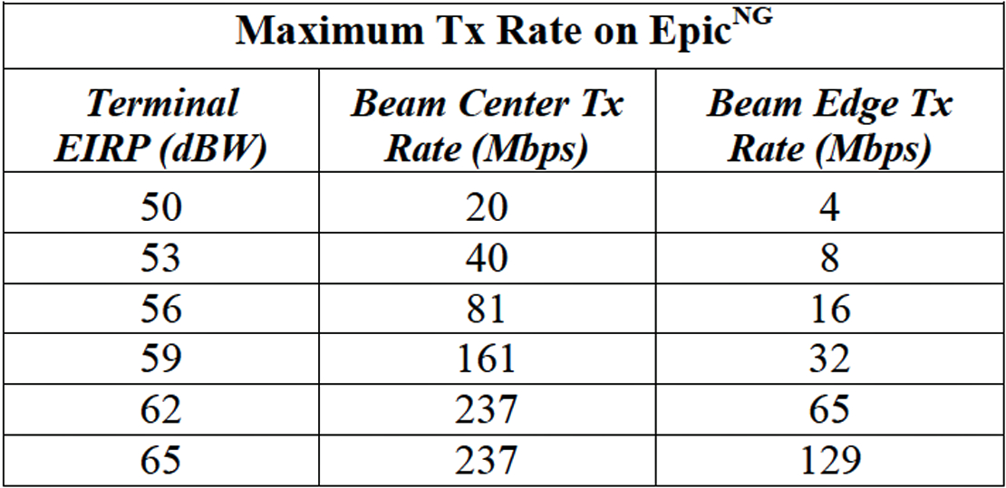
Table IV. Intelsat Epic NG Efficiency With 7.3 Meter Hub
LBAs were completed for remote terminals ranging from 30 centimeters to 1.2 meters in diameter; located at beam center and beam edge. Performance parameters of the remote terminals are shown in Table I.
LBAs were completed for sample carrier sizes with allocated bandwidth (BW) equal to power equivalent bandwidth (PEB)—which provides optimal satellite efficiency—unless constrained by off-axis emission limits. For the configuration analyzed, off-axis emissions limited transmissions for terminals smaller than 76 centimeters. The LBA results can be scaled to a desired carrier size and/or a desired satellite resource allocation.
Typical AISR terminal antennas range from 30 centimeters to 1.2 meters. Return link performance for those antenna sizes, at beam center, is detailed in the two Table IIs below, which shows results for both (a) constant 10 Mbps transmission rate and (b) constant 4.1 MHz of satellite resources.
Table III details the DVB-S2 modulation and forward error correction (FEC) coding achieved in both sections of Table II. The corresponding satellite efficiencies are also provided.
Note that the results in Table II are determined assuming operation at the maximum possible satellite efficiency, i.e., with highest aggregate Mbps per transponder. Higher throughputs are possible—for an individual terminal EIRP—by using less satellite-efficient modulation and coding rates.
The transmit EIRP values in Table II are 1 dB over normal LBA results to compensate for an assumed 1 dB radome loss. HPA sizes in Table II assume a 0.5 dB loss between HPA output and antenna flange.
If a terminal’s Tx EIRP capability is different from that shown in Table II, the data rate and satellite resources can be scaled accordingly. The satellite efficiency will remain the same.
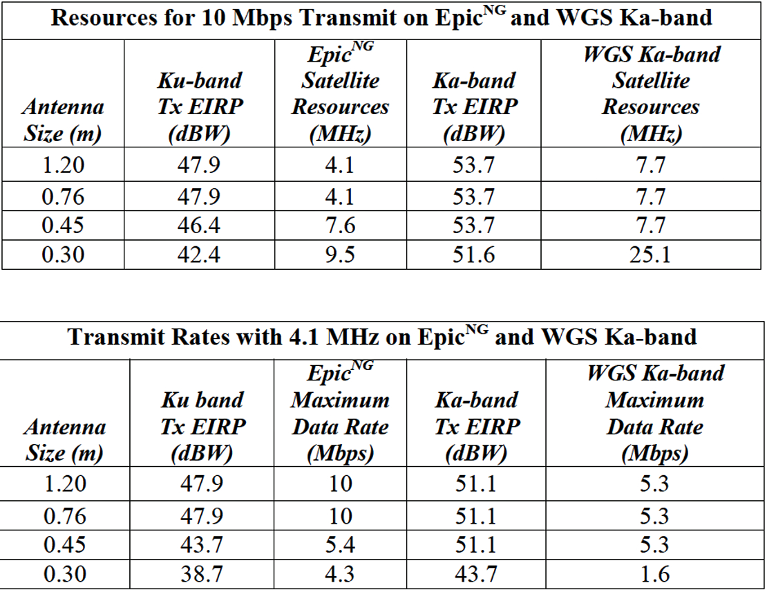
Table V. Epic NG Ku-Band Vs. WGS Ka-Band Return Link.
The high G/T on Intelsat EpicNG satellites leads to multiple efficiency gains for AISR terminals. First, the high G/T results in lower terminal EIRP and corresponding lower off-axis emissions. Due to this, carrier spreading is not required when transmitting from a 45 or 30 centimeter terminals on EpicNG. This differs radically from traditional Ku-band satellites, which typically require 2 to 4 times spreading for, respectively, 45 and 30 centimeter antennas.
The lack of spreading on EpicNG translates directly into bandwidth savings for the User. Additional savings are realized when more efficient modulations and coding are utilized; e.g., QPSK, 5/6 listed in Table III instead of the QPSK, ½ that is typical today.
A second efficiency gain derives from the fact that transmissions from 76 centimeter terminals and larger can readily operate at maximum satellite efficiency on Intelsat EpicNG—i.e., operate with occupied MHz equaling PEB. This is due to their EIRP capabilities and off-axis isolation.
With these efficiencies, any 76 centimeter or larger terminal, capable of 53 dBW EIRP, can uplink up to 40 Mbps on EpicNG at beam center and 8 Mbps at beam edge.
Table IV describes maximum return link capacities at beam center and beam edge on Intelsat EpicNG for a range of terminal EIRPs. As in Table II, the values in Table IV are achieved while operating at maximum satellite bps/Hz efficiency. Also as before, for a given EIRP, higher throughputs are possible, up to transponder bandwidth limits, but at the cost of lower satellite efficiency.
A common terminal size for airborne satellite communications is 45 centimeter (18-inch) with maximum transmit EIRP of 44 dBW. On existing Ku-band satellites, this terminal typically achieves 1.0 to 1.5 Mbps transmission rates while occupying, respectively, 5 MHz and 7.5 MHz, due to spreading.
These are nominal beam edge / beam center values. On Intelsat EpicNG, performance improves to 4 Mbps in 4 MHz at beam edge and 7.6 Mbps in 5.5 MHz at beam center. This is a fourfold increase in transmit bit rate with a simultaneous 20% decrease in satellite MHz.
Intelsat EpicNG Performance Comparisons To Ka-Band Systems
From [1], future AISR systems will likely support commercial Ku- as well as military Ka-band satellites (i.e., WGS). In [7], analysis was performed showing link performance of WGS and legacy Eutelsat Ku-band, focused on the benefits of the DVB-S2 ACM properties. This article section updates the analysis to include AISR terminals and the Intelsat EpicNG satellites. Link budgets parameters for the Ka-band system are taken from [12] .
Table V compares Intelsat EpicNG and US DoD Wideband Global SATCOM (WGS) Ka-band performance for representative AISR systems. Link performance parameters, in terms of availability and bit error rate, are kept constant.
As done earlier, two comparison scenarios are explored: one showing bandwidth resources required for a fixed 10 Mbps data rate and a second showing the data rate possible with a fixed 4.1 MHz of satellite resource. With higher G/T versus legacy Ku-band, EpicNG offers equal to superior performance to WGS Ka-band in all cases.
The results in Table V are for the following conditions:
• Ka-band terminal EIRP is the power-controlled value optimized for aggregate transponder capacity (1.2m, 0.76m, 0.45m) or as limited by off-axis energy constraints (0.30m)
• Ka-band Satellite performance from [12]
• Modem implementation loss assumed at 1 dB @ BER = 1e-8
• DVB-S2 with ª = 0.25
• Availability = 99 percent ITU-Model 7 with terminal @ 30k feet altitude
In Conclusion
UAS roadmap documents [1] identify commercial Ku-band SATCOM as an essential part of current and future AISR systems. In this paper, we extend the results from [3] to identify the opportunities with the Intelsat EpicNG satellites to improve UAS performance and AISR missions. Identified is a 4x transmit data rate improvement for existing AISR terminals on Intelsat EpicNG when compared to wide beam legacy Ku-band satellites.
On EpicNG, existing small AISR terminals are enabled to 7.6 Mbps transmissions and large larger terminals up to 237 Mbps. A comparison was also made to WGS military Ka-band capabilities, showing that EpicNG offers equal to better performance than WGS across a range of terminal sizes.
Based on the analysis in this article, future AISR mission performance will be much improved using EpicNG and WGS Ka-band over legacy systems.
Direct link to the Intelsat General infosite for the white paper:
intelsatgeneral.com/document/aisr-missions-intelsat-epicng-ku-band/
Intelsat General also offers an interesting video that presents Protected Communications and describes the anti-jamming features on the
Intelsat EpicNG satellites that are mentioned in this article. That link is:
intelsatgeneral.com/videos/protected-and-secure-satellite-communications/
References
[1] Department of Defense United States of America, “Unmanned systems integrated roadmap (FY2013-2038),” Open Publication Reference Number 14-S-0553.
[2] Intelsat EpicNG websites, http://www.Intelsatgeneral.com/node/642, http://www.Intelsat.com/infrastructure/Intelsat-epicng/, 1 May 2014.
[3] C. McLain, S. Panthi, M. Sturza, and J. Hetrick, “High throughput Ku-band satellites for aeronautical applications,” IEEE MILCOM 2012.
[4] G. Nicola, M. Franci, “Rocket science made simple - satellite connectivity for aviation explained,” http://www.inmarsat.com/wp-content/uploads/2013/10/Inmarsat_Rocket_Science_Made_Simple.pdf.
[5] Headquarters, US Air Force, “United States Air Force RPA vector – vision and enabling concepts 2013-2038,” February 2014.
[6] L-3 PPDL Dat Sheet, http://www2.l-3com.com/csw/ProductsAndServices/DataSheets/Ku-band_SATCOM_Data-Link_%28KuSDL%29_Predator_Sales-Sheet_WEB.pdf, 1 May 2014.
[7] B. Bennett, D. Hannan, J. Marshall, R. Gibbons, “Link analysis of commercial and wideband gapfiller satellite (WGS) satellites using DVB-S2 with variable coding and modulation (VCM),” IEEE MILCOM 2006.
[8] C. Timmerman, M. Wright, and T. Brick, “Extension of DVB-S2 capabilites for high-rate ASIR data transport,” IEEE MILCOM 2009.
[9] L. Wang and D. Ferguson, “WGS air-interface for AISR missions,” IEEE MILCOM 2007.
[10] Department of Defense United States of America, “Wireless Communications Waveform Development and Management,” DoDI 4630.09, 3 November 2008.
[11] European Telecommunications Standards Institute, “Digital Video Broadcasting (DVB); Second generation framing structure, channel coding and modulation systems for Broadcasting, Interactive Services, News Gathering and other broadband satellite applications (DVB-S2),” http://www.etsi.org/deliver/etsi_en/302300_302399/302307/01.02.01_60/en_302307v010201p.pdf, 24 August 2009.
[12] B. Bennett, K. Quock, J. Greeves, M. Nguyen, “DoD IP SATCOM transition to WGS,” IEEE MILCOM 2007.